11 minutes
Aruba Spine Leaf With OSPFv3 and IPv6
Introduction
Hello and thank you for checking out this post! In this post I hope to breakdown the topology you see above. I’ll walk through the design, IPv6 IP allocations, and OSPFv3. I have a very small background in IPv6, basically enough to get past a few Cisco exams, which inevitably gets forgotten about after some time of little to no use. I purchased IPv6 Fundamentals by Rick Graziani, I want to say almost a year ago. Its been sitting there haunting me for months.
I finally cracked it open and I can say it is incredible in getting you used to IPv6 and understanding the technologies involved. I’m about a third of the way done with the book and I hope to put some of what I’ve learned to practice in the topology above and in this post. Also, maybe helping folks learn a bit about spine leaf deployments and IPv6 in general.
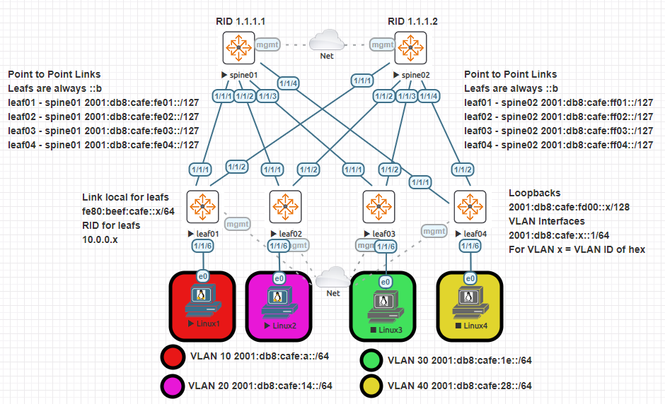
Since its just you and me here. Lets pretend our site was assigned the 2001:db8:cafe::/48 global unicast prefix. Let me tell you, this gives us a whole bunch of IP space. I mean unimaginable amounts of IP space. This prefix will be more important as we go through the post. Please note, this design is fairly basic in nature and doesn’t use any fancy stuff like EVPN/VXLAN/LAG.
Design
The design you see above is using Aruba CX nodes with version 10.06.0001 running on EVE-NG. The base of the topology is a spine leaf design. In a spine leaf design, every spine connects to every leaf. Every leaf connects to every spine. Spines do not connect with each other. In some situations, leaf switches can connect together. For example, when dual connecting a host. In the case of this topology we have two spines and four leaf nodes. The Linux nodes you see below are just running Linux Slax. They will be used for some lightweight testing and verification of connectivity.
Lets knock out a few of the simple things. I’ll be using OSPFv3 in this example. The nodes were required to have a router ID set. In this case I stuck with spine01 having 1.1.1.1, spine02 having 1.1.1.2, and so on. For the leaf nodes I used the 10.0.0.x pattern. X being the number of the leaf.
The leaf to spine connections just follow a pattern, port 1 on each leaf connects to spine01 and port 2 on each leaf connects to spine02. Speaking of the leaf to spine connections, you will notice that these are point to point connections. In the IPv4 world this would usually mean we have a /30 or /31 network on the link. IPv6 has something similar, the /127 network.
We will use a portion of the highest network in 2001:db8:cafe::/48. Connections to spine01 will be on 2001:db8:cafe:fe::/56 and connections to spine02 will be on the 2001:db8:cafe:ff::/56 network. You will probably notice the pattern I followed in the diagram. Leaf nodes will always get the ::b address and spines will be assigned the ::a address.
At this point you might be thinking, wow this is wasting a lot of IP space. Remember, with IPv6 you have an incredible amount of IP space. This doesn’t mean you shouldn’t plan ahead but also don’t spend months on this. One small caveat, I’m not saying this is a great or even good IP plan for this deployment. Just going by what I’ve learned so far and putting it to use. Below you’ll see the link configurations on spine01. The output for spine02 is essentially the same.
OSPFv3 and Spine Nodes
Spine01 Configuration
!
interface mgmt
     no shutdown
     ip dhcp
interface 1/1/1
     no shutdown
     description link to leaf01
     ipv6 address link-local fe80:face:cafe::1/64
     ipv6 address 2001:db8:cafe:fe01::a/127
     ipv6 ospfv3 1 area 0.0.0.0
     no ipv6 ospfv3 passive
     ipv6 ospfv3 network point-to-point
     ipv6 ospfv3 bfd
interface 1/1/2
     no shutdown
     description link to leaf02
     ipv6 address link-local fe80:face:cafe::1/64
     ipv6 address 2001:db8:cafe:fe02::a/127
     ipv6 ospfv3 1 area 0.0.0.0
     no ipv6 ospfv3 passive
     ipv6 ospfv3 network point-to-point
     ipv6 ospfv3 bfd
interface 1/1/3
     no shutdown
     description link to leaf03
     ipv6 address link-local fe80:face:cafe::1/64
     ipv6 address 2001:db8:cafe:fe03::a/127
     ipv6 ospfv3 1 area 0.0.0.0
     no ipv6 ospfv3 passive
     ipv6 ospfv3 network point-to-point
     ipv6 ospfv3 bfd
interface 1/1/4
     no shutdown
     description link to leaf04
     ipv6 address link-local fe80:face:cafe::1/64
     ipv6 address 2001:db8:cafe:fe04::a/127
     ipv6 ospfv3 1 area 0.0.0.0
     no ipv6 ospfv3 passive
     ipv6 ospfv3 network point-to-point
     ipv6 ospfv3 bfd
interface loopback 0
     ipv6 address link-local fe80:face:cafe::1/64
     ipv6 address 2001:db8:cafe:ffff::1/128
     ipv6 ospfv3 1 area 0.0.0.0
!
router ospfv3 1
     router-id 1.1.1.1
     passive-interface default
     area 0.0.0.0
!
A lot to unpack there right? Ill do my best to break it down below. Lets just focus on the small snippet below.
Interface Snippet
interface 1/1/4
     no shutdown
     description link to leaf04
     ipv6 address link-local fe80:face:cafe::1/64
     ipv6 address 2001:db8:cafe:fe04::a/127
     ipv6 ospfv3 1 area 0.0.0.0
     no ipv6 ospfv3 passive
     ipv6 ospfv3 network point-to-point
     ipv6 ospfv3 bfd
!
router ospfv3 1
     router-id 1.1.1.1
     passive-interface default
     area 0.0.0.0
The link local address comes with every IPv6 enabled interface. Whether its Windows, Mac, or whatever. Doesn’t matter. You can leave this alone and the device will generate a link local address on its own. In our world, its better to just configure the link local address ourselves. This helps when working with routing protocols and figuring out what the source of traffic may be. You can configure the same link local address on each interface of a device. Link local addresses start with fe80, and as you can see, I’ve assigned the same throughout each interface.
Not much to add on the global unicast address (2001:). This is following the plan mentioned above. Note that all spine01 GUA end in ::a. “ipv6 ospfv3 1 area 0.0.0.0”, just enabling OSPF under the interface. One good thing to note, if you noticed there is “no ipv6 ospfv3 passive” under each point to point interface. By default we are setting each OSPF enabled interface to passive.
This is a good way of limiting the amount of chatter in a OSPF network. This will also skip some OSPF states since no DR/BDR elections occur or even need to occur on point to point links. Under the main OSPFv3 configuration; we are setting every interface to passive by default, setting router ID, and activating area 0. Bidirectional forwarding detection (BFD) is enabled under each point to point interface to help with failure detection on links.
I want to take a quick second and mention IP unnumbered. This does seem like a lot of IP addresses to manage, even if we are following a pattern. To my knowledge and some google searches, I don’t believe Aruba supports this feature. IP unnumbered essentially lets you borrow an IP address from an interface. For example, borrowing the loopback 0 address in our deployment and using it on all point to point links. If your network operating system supports this feature, use it! I think that’s enough for the spines, lets take a look at one of the leaf nodes. Below is leaf01, again, all other leaf nodes are essentially the same.
OSPFv3 and Leaf Nodes
Leaf01 Configuration
vlan 1,10
interface 1/1/1
     no shutdown
     description link to spine01
     ipv6 address link-local fe80:beef:cafe::1/64
     ipv6 address 2001:db8:cafe:fe01::b/127
     ipv6 ospfv3 1 area 0.0.0.0
     no ipv6 ospfv3 passive
     ipv6 ospfv3 network point-to-point
     ipv6 ospfv3 bfd
interface 1/1/2
     no shutdown
     description link to spine02
     ipv6 address link-local fe80:beef:cafe::1/64
     ipv6 address 2001:db8:cafe:ff01::b/127
     ipv6 ospfv3 1 area 0.0.0.0
     no ipv6 ospfv3 passive
     ipv6 ospfv3 network point-to-point
     ipv6 ospfv3 bfd
interface 1/1/6
     no shutdown
     description link to Linux1
     no routing
     vlan access 10
interface loopback 0
     ipv6 address link-local fe80:beef:cafe::1/64
     ipv6 address 2001:db8:cafe:fd00::1/128
     ipv6 ospfv3 1 area 0.0.0.0
interface vlan 10
     ipv6 address link-local fe80:beef:cafe::1/64
     ipv6 address 2001:db8:cafe:a::1/64
     no ipv6 nd suppress-ra
     ipv6 ospfv3 1 area 0.0.0.0
!
router ospfv3 1
     router-id 10.0.0.1
     passive-interface default
     area 0.0.0.0
Looks fairly similar right? Lets just focus on the new stuff. I added VLAN 10 on leaf01, VLAN 20 on leaf02, and so on. After that I just assigned the host interface to the appropriate VLAN. Here is where things get fun. In hex you get the range of 1-15. A-F make up what we know as 10-15. Remember our whole network is 2001:db8:cafe::/48. I decided to use the next available prefix that matched the VLAN number.
For example if the VLAN is 10, that would give us 2001:db8:cafe:a::/64. If the VLAN was 20, that would give us 2001:db8:cafe:14::/64. Looking at that last IP, the 1 in 14 is in the 16’s place, so that adds up to 16, and the 4 is in the 1’s place. 16 + 4 = 20, or VLAN 20. Now you might be wondering, why are you using a /64. Well, the powers that be recommend all LAN networks be a /64. This helps nodes acquire addresses automatically without a DHCP server. More on that in a sec. The /64 would give you over 18,000,000,000,000,000,000 possible Interface IDs…. on one LAN… wow.
Hosts
You may have wondered, what does the “no ipv6 nd suppress-ra” command do? This is a great time to talk about hosts or end devices. Usually these systems will have static addresses for management and tracking. I left the Linux hosts as default so they could use the built in processes with IPv6 to acquire an address. Back to the /64 prefix size. We have just split the 128 bit address in half. 64 are for the prefix/subnet and what’s left are for hosts, called an interface ID in IPv6.
In IPv6 hosts can use a process called SLAAC (stateless address autoconfiguration). I wont go deep into details but essentially the host sends router solicitation (RS) messages and the router responds with router advertisement (RA) messages. The host uses the information in the RA message, with the prefix to determine how to go about getting an interface ID.
In our case the host will use EUI-64. Another new thing! This ones not so bad. Essentially the host uses its 48 bit MAC address, splits it in half to insert FFFE in the middle, and then flips the seventh bit to make it a zero or a one. Don’t worry if its over your head. Just know the host uses its MAC to build the interface ID and inserts FFFE in the middle!
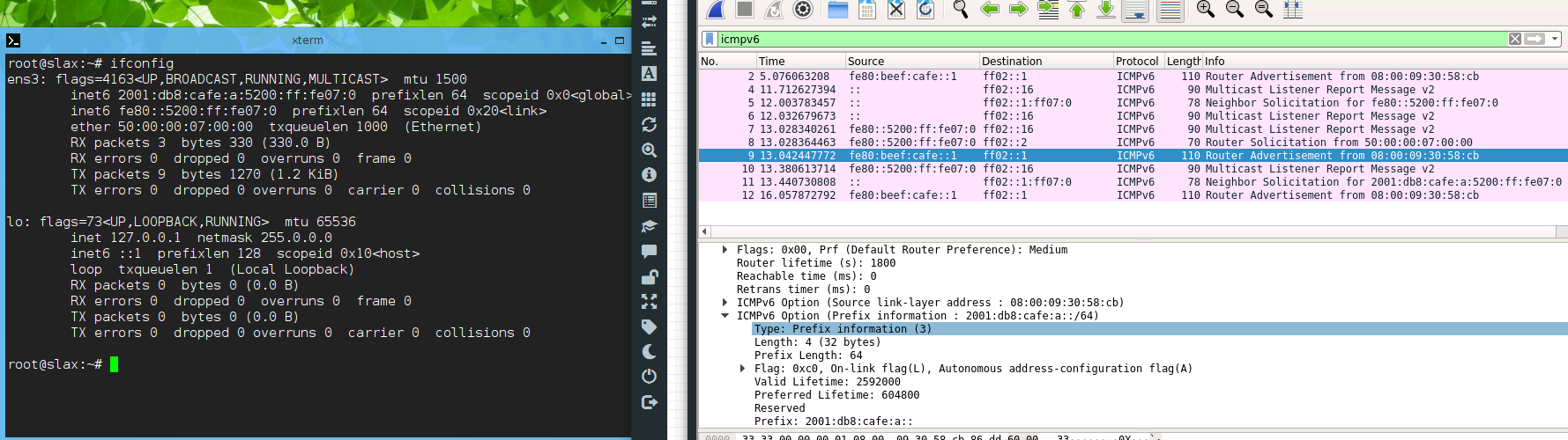
Back to our “no ipv6 nd suppress-ra” command. From my testing it seems that Aruba CX devices wont send the RA message needed by the hosts by default. In this case, just add that command and away you go. I’ll finish the technical stuff with a snap of Wireshark between Linux1 and leaf01
Packet capture between leaf01 and linux01
Packet Information
| Packet # | Type | Description |
|---|---|---|
| 8 | Router Solicitation (RS) | Linux1 using its link local address (fe80:5200:ff:fe07:0) to reach the All-routers address (ff02::2) |
| 9 | Router Advertisement (RA) | leaf01 using its link local address (fe80:beef:cafe::1) to reach the All-nodes address (ff02::1) |
Check out the ICMPv6 options sent in the RA message. The big one to note here is the prefix information of 2001:db8:cafe:a::/64, the VLAN 10 prefix information on leaf01. Just a note, the RA message is also the only way a node can get a default gateway in IPv6. Whether its SLAAC or DHCPv6, the default gateway comes from the RA message.
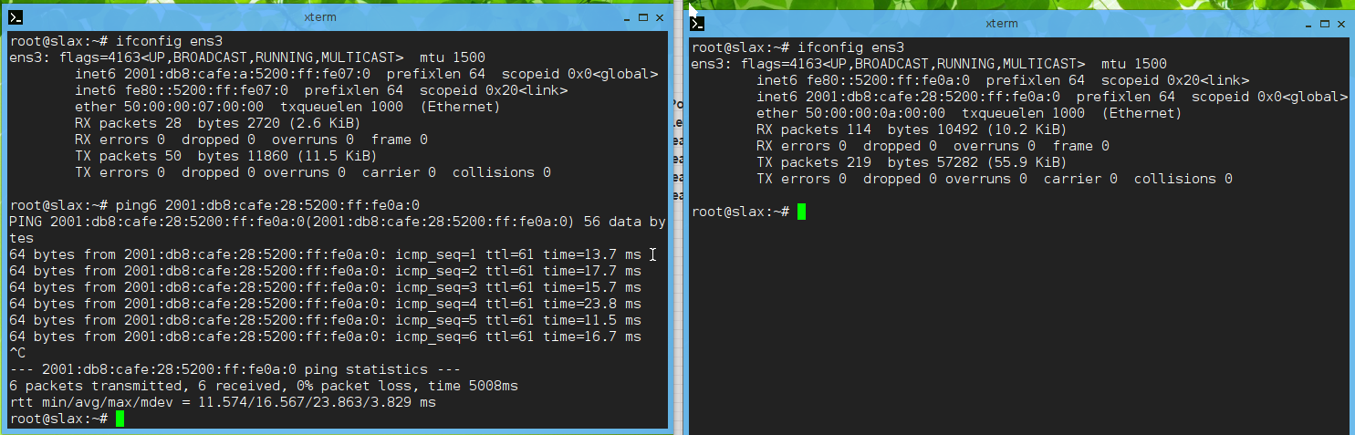
What’s a good network engineering article without some routes and pings!
OSPFv3 Routes at leaf01
leaf01# show ipv6 ospfv3 routes | b 2001
 2001:db8:cafe:a::/64 (i) area:0.0.0.0
      directly attached to interface vlan10, cost 100 distance 110
 2001:db8:cafe:14::/64 (i) area:0.0.0.0
      via fe80:face:cafe::1 interface 1/1/1, cost 300 distance 110
 2001:db8:cafe:14::/64 (i) area:0.0.0.0
      via fe80:face:cafe::2 interface 1/1/2, cost 300 distance 110
 2001:db8:cafe:1e::/64 (i) area:0.0.0.0
      via fe80:face:cafe::1 interface 1/1/1, cost 300 distance 110
 2001:db8:cafe:1e::/64 (i) area:0.0.0.0
      via fe80:face:cafe::2 interface 1/1/2, cost 300 distance 110
 2001:db8:cafe:28::/64 (i) area:0.0.0.0
      via fe80:face:cafe::1 interface 1/1/1, cost 300 distance 110
 2001:db8:cafe:28::/64 (i) area:0.0.0.0
      via fe80:face:cafe::2 interface 1/1/2, cost 300 distance 110
 2001:db8:cafe:fd00::2/128 (i) area:0.0.0.0
      via fe80:face:cafe::1 interface 1/1/1, cost 200 distance 110
 2001:db8:cafe:fd00::2/128 (i) area:0.0.0.0
      via fe80:face:cafe::2 interface 1/1/2, cost 200 distance 110
 2001:db8:cafe:fd00::3/128 (i) area:0.0.0.0
      via fe80:face:cafe::1 interface 1/1/1, cost 200 distance 110
 2001:db8:cafe:fd00::3/128 (i) area:0.0.0.0
      via fe80:face:cafe::2 interface 1/1/2, cost 200 distance 110
 2001:db8:cafe:fd00::4/128 (i) area:0.0.0.0
      via fe80:face:cafe::1 interface 1/1/1, cost 200 distance 110
 2001:db8:cafe:fd00::4/128 (i) area:0.0.0.0
      via fe80:face:cafe::2 interface 1/1/2, cost 200 distance 110
 2001:db8:cafe:fe01::a/127 (i) area:0.0.0.0
      directly attached to interface 1/1/1, cost 100 distance 110
 2001:db8:cafe:fe02::a/127 (i) area:0.0.0.0
      via fe80:face:cafe::1 interface 1/1/1, cost 200 distance 110
 2001:db8:cafe:fe03::a/127 (i) area:0.0.0.0
      via fe80:face:cafe::1 interface 1/1/1, cost 200 distance 110
 2001:db8:cafe:fe04::a/127 (i) area:0.0.0.0
      via fe80:face:cafe::1 interface 1/1/1, cost 200 distance 110
 2001:db8:cafe:ff01::a/127 (i) area:0.0.0.0
      directly attached to interface 1/1/2, cost 100 distance 110
 2001:db8:cafe:ff02::a/127 (i) area:0.0.0.0
      via fe80:face:cafe::2 interface 1/1/2, cost 200 distance 110
 2001:db8:cafe:ff03::a/127 (i) area:0.0.0.0
      via fe80:face:cafe::2 interface 1/1/2, cost 200 distance 110
 2001:db8:cafe:ff04::a/127 (i) area:0.0.0.0
      via fe80:face:cafe::2 interface 1/1/2, cost 200 distance 110
 2001:db8:cafe:ffff::1/128 (i) area:0.0.0.0
      via fe80:face:cafe::1 interface 1/1/1, cost 100 distance 110
 2001:db8:cafe:ffff::2/128 (i) area:0.0.0.0
      via fe80:face:cafe::2 interface 1/1/2, cost 100 distance 110
Trace from leaf01 to VLAN 40 at leaf04
Outro and Links
Thank you so much for reading this far! I am just getting my bearings with IPv6 but it really is great. Maybe as I work through the book I’ll add some border leaf nodes and get some NAT64 going! Check out the links below if curious about learning more on IPv6 or data center networking. Too many RFCs to list but you can easily google them. For example RFC 6164, “Using 127-Bit IPv6 Prefixes on Inter-Router Links”.
- Cloud Native Data Center Networking: Architecture, Protocols, and Tools - I cant find the free link!
- IPv6 Fundamentals: A Straightforward Approach to Understanding IPv6 Second Edition
- FYI, these are not sponsored links at all. I earn nothing if you buy or don’t buy a product.
- Follow up post: Using only link-local addresses between routers