17 minutes
My Journey and Experience With Containerlab
Introduction
Thank you all for checking out this post. This is going to be a special one. Due to the fact that I had such a joy using this new tool (new to me). I don’t like to over hype tools or new things just to hype it up. There are times where a tool or technology does deserve the credit and time in the limelight. I think Containerlabs is one of those tools.
Where are we?
Before I get started on defining Containerlab, I think its important to mention where we have come from in the networking industry. In the past when a learner or fellow engineer wanted to test a technology, design, or topology, they would have to acquire physical gear. This would take up a lot of space, power, and can you imagine the cost back in the day? I say back in the day like it was 30 years ago. More like less than 10.
The next phase added virtual versions of network operating systems, these could then be added to some hypervisor and stand up a virtual lab. Much more efficient but still required a lot of steps to get going and now required a server or some machine to host all the virtual machines. In the last few years, tools have sprung up to make this process even more simple (EVE-NG, GNS3, CML2).
I don’t want to knock these tools as I still think they are pretty incredible and provide a lot of useful features. Like anything in tech, there are trade offs. With any of these tools, there is still a requirement to have a VM or workstation available that can run said tool and then run your NOS images. For the most part these can be CPU and memory intensive, depending on the image. The process of adding the individual images can be a pain as well depending on the tool itself.
Why Containerlab?
So this is where Containerlab comes in. If you read my previous CI/CD blog series, I mentioned how quick and easy it was to get applications going by just running a packaged Docker container. This could be Drone, Batfish, or Suzeiq. Imagine that simplicity but for networking images. Containerlab was created to simplify the process of creating networking topologies within a Docker environment. I’ll do my best to walk you through some of the features of Containerlab and hopefully you walk away as impressed as I was.
Getting Started With Containerlab
One of the main requirements of Containerlab is to have an environment with Linux and Docker available. In my case, I am running a Linux laptop running PopOS. For instructions on getting Docker installed, please see this example by the team at Digital Ocean.
Installing Containerlab
# download and install the latest release (may require sudo)
bash -c "$(curl -sL https://get-clab.srlinux.dev)"
How to Add Networking Images to Containerlab
At this time there are a few network vendors that make acquiring container images for their NOS simple. Nokia (SR Linux) is a great example of that. In their case, you can just pull the image from a public repository to make it available to Containerlab. Others may require you to sign up for some guest account in their portal to get access to images. There are some that make you pick up the old telephone and ask for access, and others that don’t make any of these an option. To all vendors “please make container images of your NOS and make it publicly available”. I will walk through the process of adding an Arista cEOS image to be used with Containerlab.
- Create Arista account, image access should be available right after verifying
- Head to software downloads

Now that the image is downloaded, we need to make it available to Docker and Containerlab.
❯ docker import cEOS-lab-4.27.0F.tar ceos:4.27.0F
❯ docker images
REPOSITORY                        TAG            IMAGE ID       CREATED          SIZE
ceos                              4.27.0F        b7119ccccbcd   27 seconds ago   1.68GB
The Topology Definition File
Now that we have a NOS container image available, we can start the initial process of standing up a lab topology. In Containerlab, this is known as the clab file. In the root on my current directory, I will create a file called net.clab.yaml. Example of my file is below. I will break down each portion in a bit.
name: cicd
prefix: ""

mgmt:
  network: statics
  ipv4_subnet: 172.100.100.0/24

topology:
  kinds:
    ceos:
      image: ceos:4.27.0F
    linux:
      image: ghcr.io/hellt/network-multitool
  nodes:
    pdx-rtr-eos-01:
      kind: ceos
      mgmt_ipv4: 172.100.100.11
    pdx-rtr-eos-02:
      kind: ceos
      mgmt_ipv4: 172.100.100.12
    pdx-rtr-eos-03:
      kind: ceos
      mgmt_ipv4: 172.100.100.13
    pdx-rtr-eos-04:
      kind: ceos
      image: ceos:4.27.0F
      mgmt_ipv4: 172.100.100.14
    client1:
      kind: linux
      mgmt_ipv4: 172.100.100.21
    client2:
      kind: linux
      mgmt_ipv4: 172.100.100.22
  links:
    - endpoints: ["pdx-rtr-eos-01:eth1", "pdx-rtr-eos-02:eth1"]
    - endpoints: ["pdx-rtr-eos-02:eth2", "pdx-rtr-eos-03:eth1"]
    - endpoints: ["pdx-rtr-eos-03:eth2", "pdx-rtr-eos-04:eth1"]
    # Client connections
    - endpoints: ["client1:eth1", "pdx-rtr-eos-01:eth2"]
    - endpoints: ["client2:eth1", "pdx-rtr-eos-04:eth2"]
name: cicd
prefix: ""
All labs must have a name at the top of the tree. This is great if you are deploying multiple labs and will prevent any conflict between them. By default lab nodes will be named using the following structure: clab-{{lab-name}}-{{node-name}}. For my example, rtr-01 would have the name of clab-cicd-pdx-rtr-eos-01. I am setting the prefix to “”, this will remove the prefix of clab-cicd on each node. That is more of a preference and not required.
mgmt:
  network: statics
  ipv4_subnet: 172.100.100.0/24
Here we are telling Containerlab to stand up a Docker network named statics that can then be assigned to our nodes.
topology:
  kinds:
    ceos:
      image: ceos:4.27.0F
    linux:
      image: ghcr.io/hellt/network-multitool
This is something I thought was really useful. Containerlab works by defining nodes with what kind of node it is and what image will be used for that node. The kind can be something like ceos, linux, crpd, and others. The documentation does an incredible job of breaking it all down. I will link the docs at the end of this post. In this example I am setting the kind of “ceos.image = ceos:4.27.0F”. This helps remove a lot of duplication when building out topology files with similar nodes.
  nodes:
    pdx-rtr-eos-01:
      kind: ceos
      mgmt_ipv4: 172.100.100.11
    pdx-rtr-eos-02:
      kind: ceos
      mgmt_ipv4: 172.100.100.12
    pdx-rtr-eos-03:
      kind: ceos
      mgmt_ipv4: 172.100.100.13
    pdx-rtr-eos-04:
      kind: ceos
      image: ceos:4.27.0F
      mgmt_ipv4: 172.100.100.14
    client1:
      kind: linux
      mgmt_ipv4: 172.100.100.21
    client2:
      kind: linux
      mgmt_ipv4: 172.100.100.22
This is where a lot of what has been defined is tied together. I will break down the first eos node and client node. Here, pdx-rtr-eos-01, is assigned the kind of ceos and will inherit the image of “ceos:4.27.0F”. This node will then be accessible either by IP address at 172.100.100.11 or by hostname or by the docker exec commands. I will show these examples in a bit. The client image is similar, it is a kind of linux and will inherit the image of “ghcr.io/hellt/network-multitool”, a publicly available image. If you notice I never had to pull down the image myself. It was handled by Containerlab.
  links:
    - endpoints: ["pdx-rtr-eos-01:eth1", "pdx-rtr-eos-02:eth1"]
    - endpoints: ["pdx-rtr-eos-02:eth2", "pdx-rtr-eos-03:eth1"]
    - endpoints: ["pdx-rtr-eos-03:eth2", "pdx-rtr-eos-04:eth1"]
    # Client connections
    - endpoints: ["client1:eth1", "pdx-rtr-eos-01:eth2"]
    - endpoints: ["client2:eth1", "pdx-rtr-eos-04:eth2"]
The links portion is fairly simple but it does require some planning on the front end. The link numbering is defined in the Containerlab documentation and even the examples helped me create this links format. It looks fairly simple but the magic going on behind the scenes is awesome.
Deploying a Topology
I may have lost you at this point but please bear with me. Lets get to the fun stuff.
❯ time sudo containerlab deploy -t net.clab.yaml
INFO[0000] Parsing & checking topology file: net.clab.yaml
INFO[0000] Creating lab directory: /home/juliopdx/git/gcl/cicd
INFO[0000] Creating docker network: Name='statics', IPv4Subnet='172.100.100.0/24', IPv6Subnet='', MTU='1500'
INFO[0000] Creating container: client1
INFO[0000] Creating container: client2
INFO[0000] Creating container: pdx-rtr-eos-04
INFO[0000] Creating container: pdx-rtr-eos-03
INFO[0000] Creating container: pdx-rtr-eos-01
INFO[0000] Creating container: pdx-rtr-eos-02
INFO[0001] Creating virtual wire: client2:eth1 <--> pdx-rtr-eos-04:eth2
INFO[0001] Creating virtual wire: pdx-rtr-eos-03:eth2 <--> pdx-rtr-eos-04:eth1
INFO[0001] Creating virtual wire: client1:eth1 <--> pdx-rtr-eos-01:eth2
INFO[0001] Creating virtual wire: pdx-rtr-eos-01:eth1 <--> pdx-rtr-eos-02:eth1
INFO[0001] Creating virtual wire: pdx-rtr-eos-02:eth2 <--> pdx-rtr-eos-03:eth1
INFO[0001] Running postdeploy actions for Arista cEOS 'pdx-rtr-eos-03' node
INFO[0001] Running postdeploy actions for Arista cEOS 'pdx-rtr-eos-04' node
INFO[0001] Running postdeploy actions for Arista cEOS 'pdx-rtr-eos-01' node
INFO[0001] Running postdeploy actions for Arista cEOS 'pdx-rtr-eos-02' node
INFO[0056] Adding containerlab host entries to /etc/hosts file
Lets walk through this a bit. Containerlab will spin up a directory named after our lab name, cicd. It will then create any management networks we have defined, in our case this will be the 172.100.100.0/24 network. After that each container is created and virtual links added. At the tail end you may have noticed that the Containerlab hosts were added to the /etc/hosts file. Containerlab is nice enough to provide a summary of everything that was deployed. Example below.
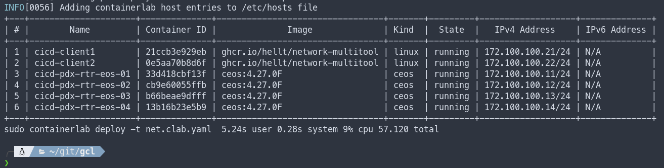
At the bottom you can see that it took 57 seconds to deploy the 4 cEOS containers and two Linux containers that will act as hosts. In theory we should be able to connect to the nodes?
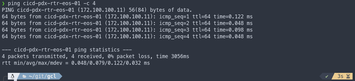
Connecting to Nodes
Great, now we have everything deployed but we need to do something with it. If folks are testing or learning a NOS, naturally we want to connect to the nodes to start laying down some sweet configuration. Luckily, we have a few options to connect to each node.
❯ ssh admin@cicd-pdx-rtr-eos-01
Password:
pdx-rtr-eos-01>en
pdx-rtr-eos-01#show version | inc image version
Software image version: 4.27.0F-24305004.4270F (engineering build)
pdx-rtr-eos-01#
❯ ssh admin@172.100.100.11
Password:
pdx-rtr-eos-01>en
pdx-rtr-eos-01#show version | inc image version
Software image version: 4.27.0F-24305004.4270F (engineering build)
pdx-rtr-eos-01#
❯ docker exec -it cicd-pdx-rtr-eos-01 Cli
pdx-rtr-eos-01>en
pdx-rtr-eos-01#show version | inc image version
Software image version: 4.27.0F-24305004.4270F (engineering build)
pdx-rtr-eos-01#
Viewing the Topology
I’m so used to using tools like GNS3 and EVE-NG. Both of these tools provide some type of GUI to view the current topology. Maybe its because I’m a visual person, but I really like to view the topology. Can you believe with a bit of digging… I found out that Containerlab can render a topology image. Example below. FYI, I don’t think the graph enjoyed all the dashes in my hostnames. I’ll post the original when I found this feature!
❯ sudo containerlab graph -t net.clab.yaml
INFO[0000] Parsing & checking topology file: net.clab.yaml
INFO[0000] Listening on :50080...
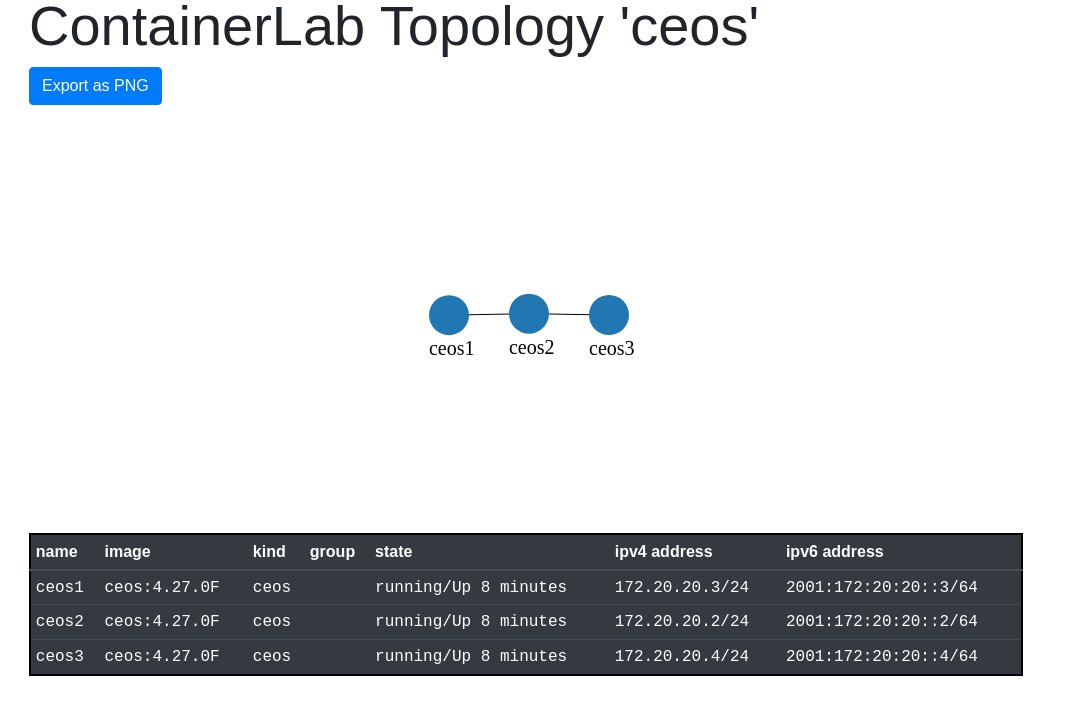
Above is the original image I generated after I found this out. Seriously awesome! I would like to see the interfaces displayed though… I know I know, we had to define this in the links so who cares? I care! I want to see them in the generated image! 🙂
Automating Some Configuration
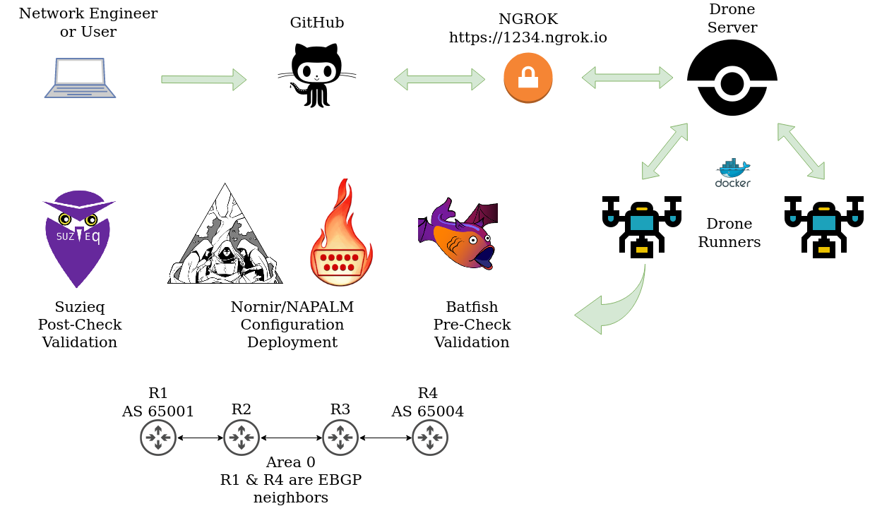
A while back I wrote a series on building a CI/CD pipeline. In that series, I used a generic topology with four Arista nodes running OSPF and BGP. I wanted to see if I could recreate this topology in Containerlab and utilize some of the automation skills I have been practicing. I wont go all in on this post but I will drop some configuration with Nornir and NAPALM using the Ansible inventory Containerlab created. Oh yeah, Containerlab creates an Ansible inventory when deploying a topology. Example of the inventory that was created after I deployed this topology is below.
all:
  children:
    ceos:
      hosts:
        cicd-pdx-rtr-eos-01:
          ansible_host: 172.100.100.11
        cicd-pdx-rtr-eos-02:
          ansible_host: 172.100.100.12
        cicd-pdx-rtr-eos-03:
          ansible_host: 172.100.100.13
        cicd-pdx-rtr-eos-04:
          ansible_host: 172.100.100.14
    linux:
      hosts:
        cicd-client1:
          ansible_host: 172.100.100.21
        cicd-client2:
          ansible_host: 172.100.100.22
Nornir With Ansible Inventory
Nornir has a plugin to interact with an Ansible inventory, after getting Nornir installed, its just a matter of installing the plugin and setting the inventory to use that plugin.
pip install nornir nornir_ansible nornir_napalm
Nornir config.yaml
---
inventory:
  plugin: AnsibleInventory
  options:
    hostsfile: "cicd/ansible-inventory.yml"

runner:
  plugin: threaded
  options:
    num_workers: 10
Below is a function used to set credentials and platform for the nodes in this deployment.
Deployment Scripts
tools.py
"""Tools script that holds a variety of functions"""

import os


def nornir_set_creds(norn, username="admin", password="admin", platform="eos"):
    """
    Handler for credentials and platform
    """
    if not username:
        username = os.environ.get("NORNIR_USER")
    if not password:
        password = os.environ.get("MY_SECRET")

    for host_obj in norn.inventory.hosts.values():
        host_obj.username = username
        host_obj.password = password
        host_obj.platform = platform
deploy.py
#!/usr/bin/env python

"""Script used to configure the network"""

from nornir import InitNornir
from nornir_utils.plugins.functions import print_result
from nornir_napalm.plugins.tasks import napalm_configure
from tools import nornir_set_creds


def deploy_network(task):
    """Configures network with Scrapli"""
    if "client" in task.host.name:
        pass
    else:
        task1_result = task.run(
            name=f"Configuring {task.host.name}!",
            task=napalm_configure,
            filename=f"configs/post/{task.host.name}.cfg",
            replace=True,
        )


def main():
    """Used to run all the things"""
    norn = InitNornir(config_file="nornir_settings/config.yaml")
    nornir_set_creds(norn)
    result = norn.run(task=deploy_network)
    print_result(result)


if __name__ == "__main__":
    main()
Sample Configuration
cicd-pdx-rtr-eos-01.cfg
! Command: show running-config
! device: pdx-rtr-eos-01 (cEOSLab, EOS-4.27.0F-24305004.4270F (engineering build))
!
no aaa root
!
username admin privilege 15 role network-admin secret sha512 $6$RxQ5ae0GOW6SAiCU$7qzQNGX2pSIqWIYBIYGF8Xh30lo/s418/diYEEZj9rPrTJiAkYv0s6AvjpTfUHMGz.a58Hg29Yy/nV0Zvplux0
!
transceiver qsfp default-mode 4x10G
!
service routing protocols model multi-agent
!
hostname pdx-rtr-eos-01
!
spanning-tree mode mstp
!
management api http-commands
   no shutdown
!
management api gnmi
   transport grpc default
!
management api netconf
   transport ssh default
!
interface Ethernet1
   description connection to pdx-rtr-eos-02
   no switchport
   ip address 10.0.12.1/24
   ip ospf network point-to-point
   ip ospf area 0.0.0.0
!
!
interface Ethernet2
   no switchport
   ip address 192.168.1.1/24
   ip ospf area 0.0.0.0
!
interface Loopback1
   ip address 10.0.0.1/32
   ip ospf area 0.0.0.0
!
interface Management0
   ip address 172.100.100.11/24
!
ip routing
!
router bgp 65001
   router-id 10.0.0.1
   timers bgp 10 30
   neighbor 10.0.0.4 remote-as 65004
   neighbor 10.0.0.4 update-source Loopback1
   neighbor 10.0.0.4 ebgp-multihop 3
!
router ospf 1
   router-id 10.0.0.1
   passive-interface Ethernet2
   passive-interface Loopback1
   max-lsa 12000
!
endtext
Script output below! I’ll set the client1 and client2 IP addresses in the meantime!
❯ docker exec -it cicd-client1 bash
bash-5.0# ifconfig eth1 192.168.1.2 netmask 255.255.255.0 up
bash-5.0# route add default gw 192.168.1.1
bash-5.0# ping -c 4 192.168.1.1
PING 192.168.1.1 (192.168.1.1) 56(84) bytes of data.
64 bytes from 192.168.1.1: icmp_seq=1 ttl=64 time=0.064 ms
64 bytes from 192.168.1.1: icmp_seq=2 ttl=64 time=0.074 ms
64 bytes from 192.168.1.1: icmp_seq=3 ttl=64 time=0.080 ms
64 bytes from 192.168.1.1: icmp_seq=4 ttl=64 time=0.073 ms

--- 192.168.1.1 ping statistics ---
4 packets transmitted, 4 received, 0% packet loss, time 3072ms
rtt min/avg/max/mdev = 0.064/0.072/0.080/0.005 ms
bash-5.0# ifconfig eth1
eth1      Link encap:Ethernet  HWaddr AA:C1:AB:94:0D:B0
          inet addr:192.168.1.2  Bcast:192.168.1.255  Mask:255.255.255.0
          inet6 addr: fe80::a8c1:abff:fe94:db0/64 Scope:Link
          UP BROADCAST RUNNING MULTICAST  MTU:9500  Metric:1
          RX packets:1754 errors:0 dropped:0 overruns:0 frame:0
          TX packets:26 errors:0 dropped:0 overruns:0 carrier:0
          collisions:0 txqueuelen:0
          RX bytes:218275 (213.1 KiB)  TX bytes:2112 (2.0 KiB)

bash-5.0# exit
❯ python deploy.py
deploy_network******************************************************************
* cicd-client1 ** changed : False **********************************************
vvvv deploy_network ** changed : False vvvvvvvvvvvvvvvvvvvvvvvvvvvvvvvvvvvvvvvvv INFO
^^^^ END deploy_network ^^^^^^^^^^^^^^^^^^^^^^^^^^^^^^^^^^^^^^^^^^^^^^^^^^^^^^^^
* cicd-client2 ** changed : False **********************************************
vvvv deploy_network ** changed : False vvvvvvvvvvvvvvvvvvvvvvvvvvvvvvvvvvvvvvvvv INFO
^^^^ END deploy_network ^^^^^^^^^^^^^^^^^^^^^^^^^^^^^^^^^^^^^^^^^^^^^^^^^^^^^^^^
* cicd-pdx-rtr-eos-01 ** changed : True ****************************************
vvvv deploy_network ** changed : False vvvvvvvvvvvvvvvvvvvvvvvvvvvvvvvvvvvvvvvvv INFO
---- Configuring cicd-pdx-rtr-eos-01! ** changed : True ------------------------ INFO
@@ -22,12 +22,37 @@
    transport ssh default
 !
 interface Ethernet1
+   description connection to pdx-rtr-eos-02
+   no switchport
+   ip address 10.0.12.1/24
+   ip ospf network point-to-point
+   ip ospf area 0.0.0.0
 !
 interface Ethernet2
+   no switchport
+   ip address 192.168.1.1/24
+   ip ospf area 0.0.0.0
+!
+interface Loopback1
+   ip address 10.0.0.1/32
+   ip ospf area 0.0.0.0
 !
 interface Management0
    ip address 172.100.100.11/24
 !
-no ip routing
+ip routing
+!
+router bgp 65001
+   router-id 10.0.0.1
+   timers bgp 10 30
+   neighbor 10.0.0.4 remote-as 65004
+   neighbor 10.0.0.4 update-source Loopback1
+   neighbor 10.0.0.4 ebgp-multihop 3
+!
+router ospf 1
+   router-id 10.0.0.1
+   passive-interface Ethernet2
+   passive-interface Loopback1
+   max-lsa 12000
 !
 end
^^^^ END deploy_network ^^^^^^^^^^^^^^^^^^^^^^^^^^^^^^^^^^^^^^^^^^^^^^^^^^^^^^^^
* cicd-pdx-rtr-eos-02 ** changed : True ****************************************
vvvv deploy_network ** changed : False vvvvvvvvvvvvvvvvvvvvvvvvvvvvvvvvvvvvvvvvv INFO
---- Configuring cicd-pdx-rtr-eos-02! ** changed : True ------------------------ INFO
@@ -22,12 +22,26 @@
    transport ssh default
 !
 interface Ethernet1
+   description connection to pdx-rtr-eos-01
+   no switchport
+   ip address 10.0.12.2/24
+   ip ospf network point-to-point
+   ip ospf area 0.0.0.0
 !
 interface Ethernet2
+   description connection to pdx-rtr-eos-03
+   no switchport
+   ip address 10.0.23.2/24
+   ip ospf network point-to-point
+   ip ospf area 0.0.0.0
 !
 interface Management0
    ip address 172.100.100.12/24
 !
-no ip routing
+ip routing
+!
+router ospf 1
+   router-id 10.0.0.2
+   max-lsa 12000
 !
 end
^^^^ END deploy_network ^^^^^^^^^^^^^^^^^^^^^^^^^^^^^^^^^^^^^^^^^^^^^^^^^^^^^^^^
* cicd-pdx-rtr-eos-03 ** changed : True ****************************************
vvvv deploy_network ** changed : False vvvvvvvvvvvvvvvvvvvvvvvvvvvvvvvvvvvvvvvvv INFO
---- Configuring cicd-pdx-rtr-eos-03! ** changed : True ------------------------ INFO
@@ -12,6 +12,8 @@
 !
 spanning-tree mode mstp
 !
+vrf instance MGMT
+!
 management api http-commands
    no shutdown
 !
@@ -22,12 +24,27 @@
    transport ssh default
 !
 interface Ethernet1
+   description connection to pdx-rtr-eos-02
+   no switchport
+   ip address 10.0.23.3/24
+   ip ospf network point-to-point
+   ip ospf area 0.0.0.0
 !
 interface Ethernet2
+   description connection to pdx-rtr-eos-04
+   no switchport
+   ip address 10.0.34.3/24
+   ip ospf network point-to-point
+   ip ospf area 0.0.0.0
 !
 interface Management0
    ip address 172.100.100.13/24
 !
-no ip routing
+ip routing
+no ip routing vrf MGMT
+!
+router ospf 1
+   router-id 10.0.0.3
+   max-lsa 12000
 !
 end
^^^^ END deploy_network ^^^^^^^^^^^^^^^^^^^^^^^^^^^^^^^^^^^^^^^^^^^^^^^^^^^^^^^^
* cicd-pdx-rtr-eos-04 ** changed : True ****************************************
vvvv deploy_network ** changed : False vvvvvvvvvvvvvvvvvvvvvvvvvvvvvvvvvvvvvvvvv INFO
---- Configuring cicd-pdx-rtr-eos-04! ** changed : True ------------------------ INFO
@@ -2,7 +2,7 @@
 !
 no aaa root
 !
-username admin privilege 15 role network-admin secret sha512 $6$80vAK4C7egYGmMCr$aQs6Oe1HPzToV9KkGBQozUNUzaelo8cM6EXUzDfsjPF4q/LJDb3WOtP01uqrCzKJWk3KpOMno40Df1nsilfwI/
+username admin privilege 15 role network-admin secret sha512 $6$RxQ5ae0GOW6SAiCU$7qzQNGX2pSIqWIYBIYGF8Xh30lo/s418/diYEEZj9rPrTJiAkYv0s6AvjpTfUHMGz.a58Hg29Yy/nV0Zvplux0
 !
 transceiver qsfp default-mode 4x10G
 !
@@ -22,12 +22,37 @@
    transport ssh default
 !
 interface Ethernet1
+   description connection to pdx-rtr-eos-03
+   no switchport
+   ip address 10.0.34.4/24
+   ip ospf network point-to-point
+   ip ospf area 0.0.0.0
 !
 interface Ethernet2
+   no switchport
+   ip address 192.168.4.1/24
+   ip ospf area 0.0.0.0
+!
+interface Loopback1
+   ip address 10.0.0.4/32
+   ip ospf area 0.0.0.0
 !
 interface Management0
    ip address 172.100.100.14/24
 !
-no ip routing
+ip routing
+!
+router bgp 65004
+   router-id 10.0.0.4
+   timers bgp 10 30
+   neighbor 10.0.0.1 remote-as 65001
+   neighbor 10.0.0.1 update-source Loopback1
+   neighbor 10.0.0.1 ebgp-multihop 3
+!
+router ospf 1
+   router-id 10.0.0.4
+   passive-interface Ethernet2
+   passive-interface Loopback1
+   max-lsa 12000
 !
 end
^^^^ END deploy_network ^^^^^^^^^^^^^^^^^^^^^^^^^^^^^^^^^^^^^^^^^^^^^^^^^^^^^^^^
Simple Verifications
pdx-rtr-eos-01#show ip ospf neighbor
Neighbor ID     Instance VRF      Pri State                  Dead Time   Address         Interface
10.0.0.2        1        default  0   FULL                   00:00:38    10.0.12.2       Ethernet1
pdx-rtr-eos-01#show ip route ospf

 O        10.0.0.4/32 [110/40] via 10.0.12.2, Ethernet1
 O        10.0.23.0/24 [110/20] via 10.0.12.2, Ethernet1
 O        10.0.34.0/24 [110/30] via 10.0.12.2, Ethernet1
 O        192.168.4.0/24 [110/40] via 10.0.12.2, Ethernet1

pdx-rtr-eos-01#show ip bgp summary
BGP summary information for VRF default
Router identifier 10.0.0.1, local AS number 65001
Neighbor Status Codes: m - Under maintenance
  Neighbor         V AS           MsgRcvd   MsgSent  InQ OutQ  Up/Down State   PfxRcd PfxAcc
  10.0.0.4         4 65004             86        86    0    0 00:11:34 Estab   0      0
pdx-rtr-eos-01#ping 192.168.4.1
PING 192.168.4.1 (192.168.4.1) 72(100) bytes of data.
80 bytes from 192.168.4.1: icmp_seq=1 ttl=62 time=0.164 ms
80 bytes from 192.168.4.1: icmp_seq=2 ttl=62 time=0.041 ms
80 bytes from 192.168.4.1: icmp_seq=3 ttl=62 time=0.033 ms
80 bytes from 192.168.4.1: icmp_seq=4 ttl=62 time=0.034 ms
80 bytes from 192.168.4.1: icmp_seq=5 ttl=62 time=0.033 ms

--- 192.168.4.1 ping statistics ---
5 packets transmitted, 5 received, 0% packet loss, time 0ms
rtt min/avg/max/mdev = 0.033/0.061/0.164/0.051 ms, ipg/ewma 0.094/0.110 ms
pdx-rtr-eos-01#
At this point client1 (192.168.1.2) should be able to reach client2 (192.168.4.2)
❯ docker exec -it cicd-client1 bash
bash-5.0# ping -c 4 192.168.4.2
PING 192.168.4.2 (192.168.4.2) 56(84) bytes of data.
64 bytes from 192.168.4.2: icmp_seq=1 ttl=60 time=0.202 ms
64 bytes from 192.168.4.2: icmp_seq=2 ttl=60 time=0.186 ms
64 bytes from 192.168.4.2: icmp_seq=3 ttl=60 time=0.215 ms
64 bytes from 192.168.4.2: icmp_seq=4 ttl=60 time=0.254 ms

--- 192.168.4.2 ping statistics ---
4 packets transmitted, 4 received, 0% packet loss, time 3066ms
rtt min/avg/max/mdev = 0.186/0.214/0.254/0.025 ms
bash-5.0#
Destroying a Topology
When destroying the lab there are two main options. Well really there is more but the other sounds dangerous! You can either destroy the lab which is more like shutting it down. Or you can destroy a lab and cleanup all directories/configurations that have been configured. The former will maintain configurations when you deploy again and the latter will revert to a factory reset if you will.
# Maintain configurations after shutdown
sudo containerlab destroy -t net.clab.yaml
# Destroy all configurations
sudo containerlab destroy -t net.clab.yaml --cleanup
Closing Thoughts
I think Containerlabs is pretty freaking awesome. The fact that I can deploy this topology in under a minute is crazy and just from my laptop. I can see Containerlab in so many different avenues. Architects testing out a design, Engineers doing it all, or students on their initial journey down the networking path or IT in general. One of the coolest things that comes to mind is Containerlab in a classroom settings. Just imagine the Instructor or teacher creates a topology file. At this point were assuming the class has a Linux system and Docker installed. The instructor then says “Okay students today we’ll be going over topology <insert awesome topology>.clab.yaml. Students then learn about why a design was chosen or the technologies involved.
Outro and Links
Thank you all so much for reading this far. I hope this wasn’t too long. GitHub repository is linked below! I was kind of building this on the fly and the documentation for Containerlab is pretty excellent. If you have any questions seriously check it out. Most all of your questions will be answered there!